Lesson 14 of the SQL Optimization Course: Index Design (B+ Tree Organization)
ytt
8 min read

For relational databases, the design of tables and SQL is written are particularly crucial. It wouldn’t be an exaggeration to say that they account for 90% of performance. So this time, specifically targeting these two major knowledge areas, we’ll conduct a detailed analysis for you, peeling back the layers.
This Series uses plain and understandable language and selects a large number of examples to elaborate on the subtleties for you.
🧑💻 Target audience:
We will use MySQL as the demonstration database.
Indexes are familiar concepts in data management. Their primary purpose is to reduce data retrieval time and minimize disk I/O operations.
Indexes are ubiquitous in data scenarios, including mobile contact lists, file systems (ext4/xfs/ntfs), and database systems (MySQL/Oracle). Database and file systems typically use B+ trees to store index information. B+ trees balance write and read performance, with extreme retrieval complexity of O(logN), where N represents the number of nodes, and logN indicates the total number of disk I/O scans.
MySQL supports four types of index structures: B+ Tree, R Tree, HASH, and FULLTEXT.
This article provides a brief introduction to B+ trees. The next article will discuss the B+ tree index implementations in MySQL’s two commonly used engines: MyISAM and InnoDB. The remaining index types will be covered in subsequent articles.
Before diving into B+ trees, let’s first understand binary trees.
Trees are data storage structures named after their resemblance to real-life trees.
An unpruned tree, as shown in Figure 1, is actually a binary tree where each node has at most two child nodes.
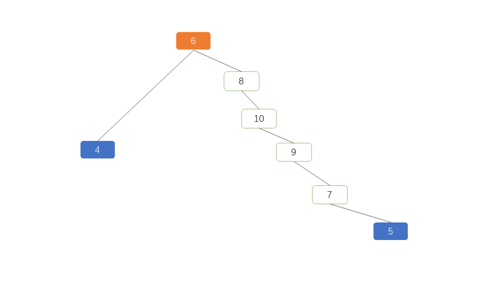
Using the tree in Figure 1 as an example:
Root Node: 6 is the root node. The root node has no parent node but has child nodes, typically called the ROOT node.
Child Nodes: 8 and 4 are child nodes of 6, with 4 being the left child and 8 the right child.
Parent Node: 6 is the parent node of 4 and 8. The parent node is the upper-level node of the child nodes.
Leaf Nodes: 4 and 5 are leaf nodes. Leaf nodes are nodes without children, except for the root node.
Sibling Nodes: 8 and 4 are sibling nodes because they share the same parent, 6. Nodes 10, 9, and 7 have no siblings as they each have only one child.
Levels: The number of layers in a tree. The tree in Figure 1 has 6 levels.
Height: The number of nodes traversed from the leaf node to the root node. The leaf node 5 to the root node traverses 7, 9, 10, 8, 6, making the height of this tree 5.
Depth: The number of nodes traversed from the root node to the leaf node. Similarly, the depth of this tree is also 5.
Height and Depth: Generally start counting from 0, though sometimes from 1.
Balance Factor: The absolute difference between the depths of a node’s left and right subtrees. If a subtree does not exist, it is treated as 0. For example, the balance factor of node 10 is 3.
Figure 1 is a very ordinary tree that can easily degenerate into a linked list. If Figure 1 is modified so that the root node becomes 4 and 6 becomes a child of 4, the tree degenerates into a linked list.
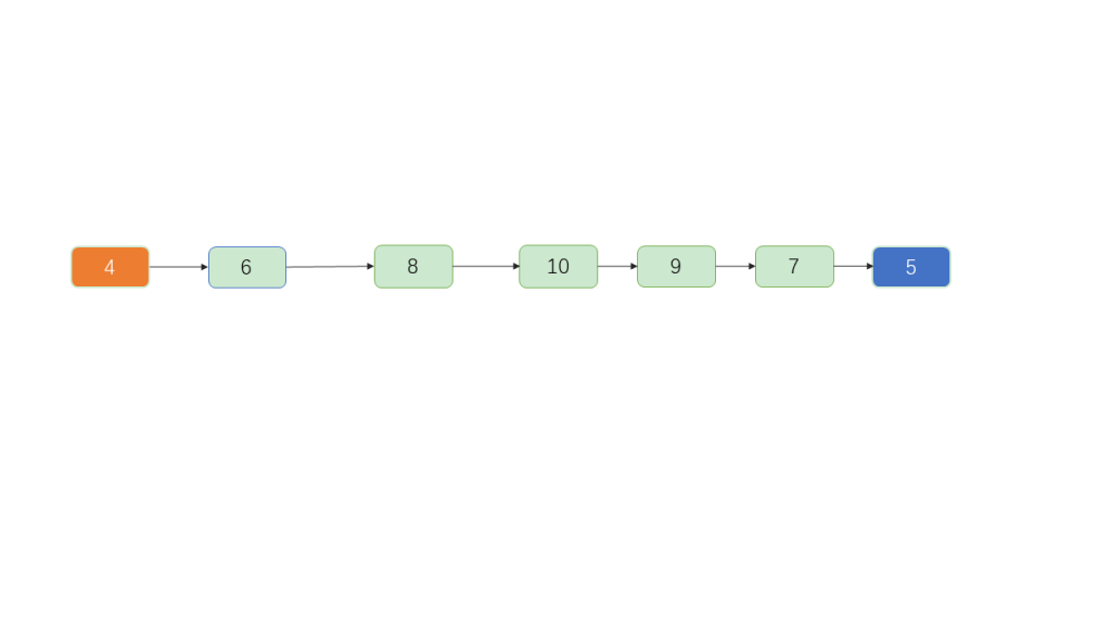
Linked lists are slow for searching, as they require sequential traversal of each node, resulting in a time complexity of O(n), with no capability for random access.
Let’s reorganize the nodes in Figure 1 to create Figure 2:
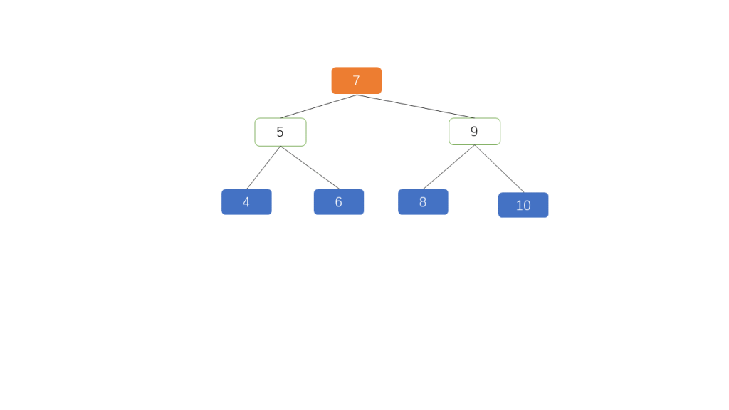
Figure 2 exhibits the following characteristics:
All nodes in the left subtree are less than their corresponding parent node (4, 5, 6) < (7); (4) < (5); (8) < (9).
All nodes in the right subtree are greater than their corresponding parent node (8, 9, 10) > (7); (6) > (5); (10) > (9).
The absolute difference in balance factors for each node is <=1.
Each node conforms to the above three characteristics.
A tree that meets these conditions is called an AVL (Adelson-Velsky and Landis) tree.
Since the data is organized in order, searches are very fast. For example, searching for 5 in the tree above only requires two traversals: 7-5. Similarly, finding the leaf node 10 would take a maximum of three traversals: 7-9-10. This means that the AVL tree performs well in search operations, with the worst-case scenario requiring a number of attempts equivalent to the tree’s height, resulting in a time complexity of O(logN).
What if there are many nodes? Suppose we have 31 nodes represented as an AVL tree in Figure 3:
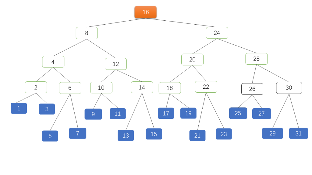
Figure 3 is an AVL tree of height 4 with 5 layers and 31 nodes. The orange node is the ROOT, and the blue nodes are the leaves. While the AVL tree’s search performance appears excellent, can it be further optimized? For instance, can the number of keys stored in each node be increased? Can the total number of tree layers be reduced? To reduce depth, we need to expand horizontally, which leads us to consider multi-way trees.
The B-Tree is a multi-way AVL tree. B-Trees reduce the height of AVL trees by increasing the number of keys per node.
Characteristics of B-Trees (m represents the order: the maximum number of child nodes a node can have):
Each node in the tree can have at most m child nodes (m >= 2).
Except for the root and leaf nodes, other nodes must have at least ceil(m / 2) children.
If the root node is not a leaf node, it must have at least two children.
Each non-leaf node contains n key information entries: (n, P0, K1, P1, K2, P2, …, Kn, Pn), where:
Ki (i=1…n) are keys, sorted in ascending order: K(i-1) < Ki.
Pi are pointers to child nodes. Pointer P(i-1) points to a child node where all keys are less than Ki but greater than K(i-1).
The number of keys n must satisfy: ceil(m / 2) - 1 <= n <= m - 1.
If a node has n keys, it has n + 1 branches. These n + 1 keys are arranged in ascending order.
All leaf nodes appear at the same level and are the endpoints of all traversals.
Following these requirements, Figure 3 is transformed into a B-Tree as shown in Figure 4:
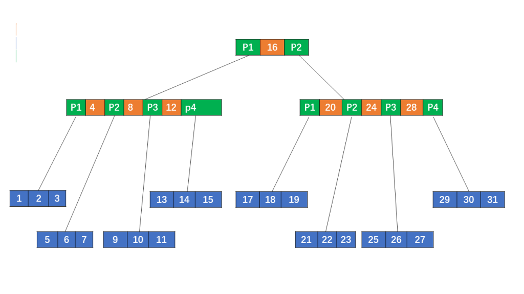
Figure 4 is a 4th-order B-Tree with a total of 11 nodes, which is 20 fewer than Figure 3, and a depth of 3, two layers less than Figure 3. In practical applications, the basic unit is not a key but a block (BLOCK). For example, the EXT4 file system uses 4KB per block; databases like PostgreSQL use 8KB, MySQL InnoDB uses 16KB, and MySQL NDB uses 32KB.
Figure 5 shows that each node’s basic unit is a disk block (BLOCK, default 4KB). The root node contains one key, while other nodes contain three keys, with each disk block holding the corresponding keys and data.
For example, to read a record with KEY 31: first, the root node’s disk block (1) is read into memory (first I/O); since KEY 31 is greater than the interval (16, ), the pointer P2 is followed to disk block 3, which is read into memory (second I/O); KEY 31 is greater than the interval (20, 24, 28), so pointer P4 is followed to read disk block 11 (third I/O). The record with KEY 31 is found in disk block 11 and the result is returned. This process involves three disk I/O reads. It is clear that the B-Tree reduces the number of nodes and the depth of the tree compared to the AVL tree, thereby reducing disk I/O.
There is, however, a problem here: the first two I/O operations actually read unnecessary data from the disk because only the KEY is needed for comparison. The DATA in non-leaf nodes is entirely unnecessary and a waste of memory resources if the DATA is large. Can the DATA in non-leaf nodes be removed?
The B+ Tree is a minor enhancement to the B-Tree. Most database indexes are based on B+ Trees. The indexes in MySQL’s MyISAM and InnoDB engines are both based on B+ Trees.
The most significant features of B+ Trees are:
Non-leaf nodes retain only KEYS and discard DATA.
KEYS and DATA are stored together in leaf nodes, which are maintained as an ordered linked list (forward, reverse, or bidirectional).
B+ Tree searches differ from B-Trees. When a node’s KEY matches the search KEY, the search does not stop but continues along the left pointer of that KEY until the corresponding leaf node is reached.
Adjusting the B-Tree in Figure 5 into a B+ Tree as shown in Figure 6:
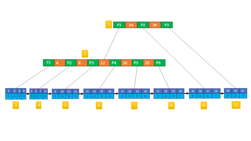
Figure 6 is a 6th-order B+ Tree. Unlike Figure 5, non-leaf nodes no longer contain data other than the primary key. All data is stored in leaf nodes, which are linked in a single-directional linked list (though they can also be bidirectional). The B+ Tree combines the advantages of balanced multi-way trees and linked lists, making it efficient for both range queries (like B-Trees) and random writes (like linked lists). This is why most databases use B+ Trees for index storage.
This article sets the stage for the next installment, which will delve into the index structures of MySQL’s two commonly used engines: MyISAM and InnoDB. Stay tuned for the next episode.
👋 See you in the next lesson.
SQLFlash is your AI-powered SQL Optimization Partner.
Based on AI models, we accurately identify SQL performance bottlenecks and optimize query performance, freeing you from the cumbersome SQL tuning process so you can fully focus on developing and implementing business logic.
Join us and experience the power of SQLFlash today!.